

Elbows are among the first components to fail in an abrasive conveying line. As particles turn, inertia drives them toward the outer radius, where repeated impacts and sliding contact remove material. Once the wall becomes thin, the plant faces leakage, contamination, unplanned shutdown, and possible damage to nearby equipment. Replacing a standard steel bend with a thicker steel bend may delay the problem, but it does not necessarily change the wear mechanism.
A wear-resistant ceramic-lined elbow adds a hard inner barrier at the surface exposed to the product stream. The concept is simple; the engineering is not. Performance depends on the conveyed material, velocity, solids loading, bend radius, angle, pipe orientation, pressure, temperature, ceramic grade, lining thickness, joint pattern, attachment method, and installation quality.
This guide provides a practical framework for selecting ceramic-lined pipe elbows for pneumatic conveying, ash handling, mineral transport, cement, coal, chemicals, and selected slurry services. It also explains what information a buyer should include in a request for quotation and how to compare suppliers without relying on vague “times longer” claims.
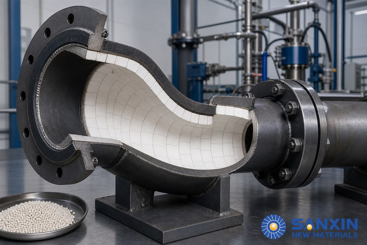
In a straight run, particles generally travel in the direction of the pipe. They may bounce, slide, or remain suspended depending on velocity, particle size, gas or liquid properties, and line orientation. At a bend, the flow direction changes while each particle tends to continue along its previous path. The outer wall must redirect it. This concentrates impact and sliding wear over a relatively small area.
The exact wear scar is application-specific. A dilute-phase pneumatic line carrying fine powder at high gas velocity may create a polished erosion zone. A dense-phase system may produce plug-related impact and complex local wear. A gravity-assisted bend can accumulate material at the bottom. A slurry elbow may experience erosion-corrosion, cavitation, solids settling, or phase separation. It is therefore risky to specify an elbow only by nominal pipe size and bend angle.
Wear can also move after a component is upgraded. A more durable elbow may shift the weakest point to a downstream reducer, flange, straight spool, or instrument connection. The engineering review should include nearby components and not treat the elbow as an isolated part.
The supplier needs enough data to reconstruct the duty. Begin with the conveyed material: name, chemical composition when relevant, bulk density or slurry density, particle-size distribution, maximum particle size, particle shape, hardness or abrasiveness, moisture, and tendency to adhere. A single average particle size is not enough when occasional oversize particles drive impact damage.
Next document the process. For pneumatic conveying, provide air or gas flow, line pressure or vacuum, solids loading ratio if known, normal and maximum velocity, throughput, operating hours, and whether the system is dilute phase, dense phase, or another mode. For slurry service, include solids concentration, carrier liquid, flow rate, velocity, pressure, pH, temperature, and corrosion history.
Record the thermal profile rather than one nominal temperature. Include normal operation, startup, cleaning, upset conditions, and cycling. Adhesive, rubber, joint filler, steel, and ceramic expand differently. A temperature limit printed for one component does not automatically qualify the assembled elbow.
Finally, describe the current failure. Provide photographs, thickness readings, operating hours, position of the wear scar, leakage location, repair history, and the material and geometry of the existing bend. This evidence helps the supplier decide whether the main problem is abrasion, direct impact, corrosion-abrasion, buildup, vibration, or a combination.
Ninety-degree elbows are common, but two 45-degree bends or a custom sweep may reduce directional change at each point. The best arrangement depends on layout space, pressure drop, line support, cleanout, and particle behavior. Changing the angle can move the impact point rather than eliminate it, so any redesign should be checked as a system.
A long-radius bend changes direction more gradually and can reduce peak impact in some services. However, it increases the surface area exposed to sliding and may not be ideal for every dense-phase or sticky-material application. A short-radius elbow is compact but creates a sharper direction change. Provide centerline radius and dimensional standard rather than describing the bend as merely “long” or “short.”
Horizontal-to-vertical, vertical-to-horizontal, and horizontal-plane bends can develop different wear patterns because gravity changes the particle concentration. Show the installed orientation on the drawing. Mark the inlet and outlet, because a symmetric-looking elbow may be lined asymmetrically to protect the expected impact zone.
Specify flange standard, pressure class, facing, material, bolt-hole orientation, and whether the lining must extend to the flange face. For welded ends, give the required preparation and allowable heat-affected zone. Include grounding, electrical continuity, and static-control requirements where applicable. The lined component must integrate with the plant’s mechanical and safety standards.
Individual alumina tiles can be fitted to the internal surface with a suitable adhesive. Tiles allow the lining to follow the bend and make localized thickness changes possible. Their performance depends on full support, controlled joints, edge protection, adhesive compatibility, and a pattern that prevents particles from tracking along seams.
Small or tapered tiles conform better to tight curves. The outer radius may receive thicker pieces or a different layout because it typically sees higher wear. Bonded construction can provide a relatively smooth bore, but temperature, chemicals, vibration, and impact must remain within the attachment system’s verified capability.
An integral ceramic tube or larger fired segment reduces the number of internal joints. It can be inserted into or assembled with a steel shell. Fewer seams may improve flow continuity, but large ceramic components are more demanding to manufacture and fit. Dimensional tolerance, end sealing, support, thermal expansion, and the transition between ceramic and steel need careful design.
Sanxin publishes technical information for alumina ceramic tubes in ACT-92 and ACT-95 grades. The listed values include alumina content of at least 92% or 95%, Mohs hardness of at least 9, water absorption no more than 0.02%, and density of at least 3.60 or 3.70 g/cm³ respectively. The published dimensional range lists outside diameter from 20 to 760 mm, inside diameter from 10 to 700 mm, and length below 600 mm. These are product-page reference values, not an automatic commitment for every elbow geometry; the final drawing and quotation control.
Mechanical retention can be considered when temperature, vibration, or impact makes adhesive-only fixing unsuitable. Perforated ceramic pieces may be secured through a central weld point, sometimes combined with adhesive support. The design must prevent exposed metal fixings from becoming wear points and must account for weld quality, steel thickness, and access.
Rubber-backed ceramic can absorb impact and is useful in some low- to moderate-temperature systems. Steel-backed panels can simplify replacement. These constructions add interfaces that must be qualified: ceramic-to-rubber bond, rubber properties, steel backing, fasteners, sealing, and temperature resistance. They are not interchangeable with a rigid ceramic-lined elbow.
Sanxin’s ceramic wear-resistance part portfolio includes several lining concepts. Selection should follow the duty, not a preference for one manufacturing method.
Alumina content is commonly used to identify a ceramic grade, but it does not describe the complete microstructure or finished quality. Density, porosity, grain size, forming process, sintering, dimensional control, toughness, and surface finish also influence performance.
Request a technical data sheet for the exact product. Useful parameters include chemical composition, bulk density, water absorption or apparent porosity, hardness, flexural strength, fracture toughness, wear-test result, and recommended temperature. Ask for the test method and sample condition. Numbers from different tests should not be compared as though they were measured identically.
The grade should also be compatible with the attachment and assembly method. A very hard ceramic that is poorly supported can crack under impact. A sound ceramic secured by an adhesive outside its chemical or thermal limit can detach. The elbow is a multi-material system; the weakest interface determines the service outcome.
There is no universal lining thickness for a given pipe diameter. Thickness must be chosen from wear severity, expected impact, service interval, available flow area, weight, manufacturability, and the ability to fit the curve. The outer radius may require greater wear allowance than the inner radius.
Increasing thickness changes more than service life. It reduces internal diameter unless the steel shell is enlarged. That can increase velocity, pressure drop, and plugging risk. A step at the inlet can become an impact edge. The transition from unlined pipe to lined elbow should be smooth enough for the service and protected against undermining.
Ask the supplier to show the minimum finished bore, lining thickness by zone, joint width, tolerances, and transition details on the drawing. If a replaceable wear indicator or inspection port is required, include it before production.
The lining pattern should direct particles across ceramic faces rather than along continuous seams. Staggered joints can help prevent a straight erosion path to the steel shell. At the outer radius, the design should avoid placing a vulnerable tile edge exactly at the predicted impact line.
Gaps must be controlled. A joint that is too wide exposes filler or steel to rapid wear. A joint that is too tight may leave no allowance for manufacturing tolerance or thermal movement. The correct width and filler depend on the ceramic size, adhesive system, temperature, and assembly method.
Cut pieces deserve special attention. Narrow slivers are difficult to support and can detach. Factory-made tapered pieces or a revised pattern are preferable when they eliminate fragile fragments. End rings and terminations should be designed so the incoming stream cannot get behind the lining.
For a bid review, request a sectional drawing showing the complete circumference, outer-radius reinforcement, inlet and outlet terminations, seam orientation, and attachment method. A photo of a generic elbow cannot replace this information.
For bonded construction, ask for the adhesive product, service-temperature range, chemical resistance, mixing ratio, working time, cure schedule, and required surface preparation. Confirm whether the stated limit is continuous or short-term. Review the carrier gas, process liquid, cleaning agents, moisture, and expected thermal cycles.
The steel shell must have sufficient remaining strength and stiffness. If the elbow is new, specify material, wall thickness, manufacturing standard, weld inspection, and corrosion allowance. If an existing elbow is relined, inspect thickness, cracking, distortion, corrosion, and previous repair welds before covering the surface.
Surface preparation should remove oil, rust, mill scale, loose coating, moisture, and dust. The specified profile and cleanliness must be achieved and maintained until bonding. Full support beneath the ceramic is essential; voids can concentrate stress and allow impact to fracture a tile.
A ceramic-lined elbow can have a smoother or more stable surface than a heavily worn steel bend, but the finished bore and geometry determine hydraulic or pneumatic behavior. Confirm that the lining does not reduce the cross-section below the process requirement. Review pressure-drop calculations after the internal diameter and bend radius are finalized.
In pneumatic systems, excessively low velocity can allow material to settle, while excessive velocity can accelerate erosion. In slurry systems, solids can settle or concentrate depending on orientation and flow regime. A lining change should not be used to compensate blindly for an operating condition outside the conveying design.
Sticky products create a separate challenge. Buildup can narrow the bore, change the particle trajectory, and create plugs. Evaluate surface finish, joint profile, moisture, temperature, and cleaning access. If mechanical cleaning tools are used, confirm they will not strike or pry the lining.
An approval drawing should precede production. It should show overall dimensions, angle, centerline radius, flange details, shell thickness, ceramic type, lining thickness, finished bore, end transitions, tolerances, flow direction, lifting points, weight, and identification.
Incoming ceramic inspection can verify dimensions, visible defects, and batch documentation. During assembly, control surface preparation, adhesive mixing, tile fit, joint width, support, and cure conditions. For mechanically retained systems, inspect studs, welds, fasteners, caps, and sealants according to the approved plan.
Final inspection should include visual examination, dimensional checks, flange alignment, bore continuity, cleanliness, and identification. Depending on the specification, steel welds may require nondestructive testing and the assembled component may require a pressure or leak test. The test pressure, medium, duration, acceptance criteria, and post-test drying must be agreed before work begins.
Packing is part of quality. Ceramic-lined elbows are heavier and more impact-sensitive than unlined fittings. Use stable supports, protected flange faces, moisture control where needed, marked lifting points, and instructions that prevent workers from lifting through the ceramic bore.
Confirm the elbow’s orientation before lifting. A directional wear design installed backward may place reinforcement on the wrong side. Use the flow arrow and equipment tag on the approved drawing. Support the elbow so connected pipe loads do not distort the shell or flange.
Check flange alignment before tightening bolts. Do not pull misaligned piping into position with the flange bolts. Select gaskets and tightening procedures compatible with the service and flange standard. For welded ends, protect the lining from excessive heat and follow the approved welding sequence.
After installation, remove foreign material and inspect the bore if access is safe. Record the installation date, tag, orientation, serial or batch reference, and baseline photographs. Commission within the approved temperature and pressure limits, and monitor pressure drop, vibration, leakage, and unusual sound.
Inspection intervals should be based on consequence and experience. A critical elbow above electrical equipment or a walkway may require online thickness monitoring or more frequent shutdown inspection. A noncritical line with containment can use a different interval.
Steel-shell ultrasonic thickness measurement can indicate external wall condition, but it may not directly measure the remaining internal ceramic. Inspection ports, removable spools, borescope access, acoustic monitoring, or planned replacement may be useful depending on the service. Agree on the method before the elbow is installed.
Track operating hours and tonnage, not calendar time alone. Record process changes, particle-size excursions, velocity changes, plugs, and cleaning events. When the elbow is removed, map wear by location. That evidence can improve the next design—for example, by changing outer-radius thickness, joint pattern, bend radius, or upstream flow conditions.
The least expensive elbow to buy may be the most expensive to operate if it causes repeated shutdowns. Compare alternatives over a stated evaluation period using:
Total ownership cost = purchase + engineering + installation + planned inspections + repairs + downtime + cleanup + disposal.
Use verified plant records for the existing elbow: price, installed labor, operating hours, throughput, repairs, leaks, shutdown duration, and secondary damage. For the ceramic option, separate confirmed supplier scope from assumptions about lifetime. A laboratory abrasion result does not establish field service life by itself.
Consider a monitored trial when the application is new or the consequence of failure is high. Define success before installation: minimum operating hours or tonnage, acceptable pressure drop, no leakage, allowable wear, inspection points, and reporting frequency. This turns a marketing claim into a controlled engineering decision.
Fly ash, bottom ash, and pulverized coal can erode bends, especially at high velocity and repeated directional changes. Provide temperature, ash characteristics, conveying mode, and fire or static-control requirements.
Concentrate, tailings, backfill, and dry mineral powders vary widely in particle size and solids concentration. Slurry chemistry and corrosion must be evaluated together with abrasion.
Raw meal, clinker dust, limestone, coal, and cement powder can create different wear and buildup behavior. High process temperature and cleaning practices influence attachment selection.
Coal injection, dust collection, sinter handling, and material conveying may combine abrasion, heat, and process cycling. Elbow orientation and upset temperature are especially important.
Purity-sensitive powders may benefit from separation from the steel wall, but the full assembly—including joints, adhesive, fasteners, and cleaning method—must meet contamination and chemical-compatibility requirements.
Send the supplier the following information:
Pipe size, schedule or wall thickness, material, and applicable standard.
Elbow angle, centerline radius, orientation, flow direction, and overall dimensions.
Flange or weld-end standard, pressure class, facing, and bolt orientation.
Conveyed material, particle-size distribution, maximum particle size, density, shape, hardness, moisture, and chemistry.
Gas or liquid, flow rate, solids loading or concentration, normal and maximum velocity, pressure or vacuum, and throughput.
Normal, startup, cleaning, and upset temperatures, including cycle frequency.
Operating hours, start-stop frequency, vibration, and line-support conditions.
Existing elbow material, service life, wear map, thickness readings, and failure photographs.
Required finished bore, allowable pressure drop, lining thickness, and weight constraints.
Chemical, food-contact, electrical, fire, contamination, coating, or documentation requirements.
Inspection, NDT, pressure-test, traceability, packing, spare, and delivery requirements.
Installation scope, supervision, warranty terms, and requested performance review.
Require the quotation to identify exclusions and assumptions. Compare the same scope across bids: ceramic grade, construction, shell, lining area, drawing, quality plan, tests, documentation, packing, and delivery. A low price may simply omit inspection, transitions, fasteners, or installation support.
One common mistake is requesting “a 90-degree ceramic elbow” without a centerline radius, orientation, or operating data. Another is choosing thickness without checking the finished bore and resulting velocity.
Buyers also overfocus on ceramic hardness while ignoring joint layout and attachment. Hard ceramic cannot protect steel after it detaches. Similarly, a high advertised temperature for ceramic does not qualify the adhesive, rubber, seals, or shell for that temperature.
Another mistake is accepting a generic product photo instead of an approval drawing. The drawing should show exactly where the ceramic is located and how it terminates. Finally, avoid treating a competitor’s case-life claim as a guarantee. Ask for comparable process conditions and define a monitored acceptance plan.
No. A longer radius may reduce peak impact in some systems, but it also changes pressure drop, footprint, sliding distance, and particle behavior. Select radius using the conveying regime and layout constraints.
Not necessarily. The outer radius often receives more wear, so a zoned design may be appropriate. The supplier must show how thickness changes affect the bore, joints, and transitions.
Yes, in suitable services, but slurry velocity, solids concentration, particle size, carrier chemistry, corrosion, settling, pressure, and joint sealing must be evaluated. “Slurry” alone is not enough information.
Specify the required performance and operating conditions, then review the exact technical data. Sanxin lists ACT-92 and ACT-95 tube grades, but the correct grade and construction depend on the elbow duty and final design.
Use a compatible attachment method, prepare the substrate correctly, provide full support, control joints and cure conditions, and inspect the work. High temperature, vibration, impact, and chemicals may require mechanical retention or a composite design.
Approve the drawing, ceramic and attachment data, finished bore, flow direction, shell and flange details, inspection plan, test requirements, packing, and supplier assumptions. Review Sanxin’s wear-resistant ceramic parts and submit the operating data with the RFQ.
A ceramic-lined elbow should be selected as an engineered conveying component, not as a steel fitting with a generic hard layer. The process conditions define the wear mechanism; the geometry controls particle impact; the ceramic and attachment form a multi-material system; and the drawing and inspection plan turn the proposal into a verifiable product.
The most effective procurement conversation begins with real operating data, a wear map, and clear acceptance criteria. Sanxin New Materials can review this information and propose a suitable configuration from its ceramic wear-resistance part range. Final materials, dimensions, service limits, and performance expectations should be confirmed in the approved quotation and drawing.
Technical note: Published product-page values are included only as reference data for the named Sanxin grades. The final contract documents and site-specific engineering review govern the supplied elbow.

Submit your demand,
we will contact you ASAP.

Sanxin New Materials Co., Ltd. focus on producing and selling ceramic beads and parts such as grinding media, blasting beads, bearing ball, structure part, ceramic wear-resistant liners, Nanoparticles Nano Powder


 English
 English
 Russian
 French
 Spanish
 Portuguese
 Arabic