

Abrasion rarely damages an industrial system evenly. A chute may lose metal at the impact zone while the discharge section remains intact. A hopper can develop a narrow wear track below its inlet. A cyclone, separator, fan housing, or pipe transition may fail first at the point where particles change direction. The engineering challenge is therefore not simply to choose a hard material. It is to match the lining material, tile geometry, attachment method, and installation quality to the actual wear mechanism.
Alumina ceramic wear tiles are widely considered for equipment that handles abrasive powders, granules, ores, ash, clinker, coal, and similar bulk solids. Their value comes from combining a hard working surface with a modular lining format. Tiles can protect flat plates, curved shells, transitions, chutes, hoppers, and other shapes without replacing the entire steel structure. When properly specified, the lining becomes a maintainable wear system rather than a disposable patch.
This guide explains how plant engineers, maintenance teams, EPC contractors, and purchasing managers can evaluate alumina ceramic lining. It focuses on practical decisions: identifying the wear mode, selecting an alumina grade and tile shape, designing joints, choosing an attachment method, preparing the steel substrate, inspecting the installation, and calculating business value without relying on unsupported lifetime claims.
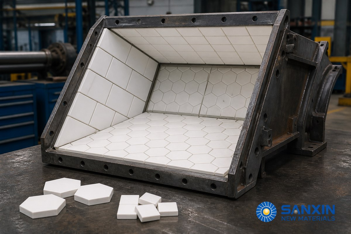
Alumina ceramic wear tiles are dense, fired ceramic components used as a sacrificial or replaceable barrier between abrasive material and structural equipment. Alumina, or aluminum oxide, provides the hard working face. The protected equipment is usually carbon steel, stainless steel, or another structural substrate that supplies mechanical strength and shape.
The ceramic does not normally replace the complete equipment body. Instead, it protects selected zones where sliding abrasion, particle erosion, or moderate impact would otherwise remove metal. Depending on the application, tiles may be bonded directly to steel, mechanically retained, welded through a central hole, embedded in rubber, or supplied as part of a steel-backed composite panel.
Common geometries include square, rectangular, hexagonal, tapered, curved, and perforated tiles. Buyers should compare tile-only systems with ceramic-rubber liners, mechanically retained liners, and factory-lined components in the wider ceramic wear-resistance parts range.
A useful specification begins with a description of how the surface is wearing. “Severe wear” is not enough. Two locations can lose the same thickness of steel per month for different reasons and may require different lining designs.
Sliding abrasion occurs when particles move along a surface under pressure. Long chutes, bins, screw-conveyor housings, and low-angle transfer points may show smooth, directional grooves. Hard ceramic surfaces can be effective here because they resist cutting by mineral particles. A smooth lining may also reduce material adhesion, although flow behavior must be verified with the actual bulk solid.
Erosion is driven by particles striking the surface at velocity. It is common in pneumatic conveying elbows, classifier housings, cyclones, dust pipes, and fan casings. The impact angle changes the damage pattern. A shallow angle tends to cut along the surface, while a steeper angle transfers more impact energy. Tile thickness alone cannot solve a poor layout at a concentrated wear point; geometry and joint orientation matter.
Large lumps dropping into a hopper or chute can fracture a brittle lining even when the material has excellent abrasion resistance. For these zones, engineers may use smaller tiles, a resilient rubber layer, a steel-backed composite, a mechanically fixed liner, or a staged impact bed. The purpose of the resilient layer is to absorb part of the impact energy and reduce stress concentration in the ceramic.
Some slurries and chemical powders combine abrasion with corrosion. In that situation, the ceramic surface may resist the process fluid, but the adhesive, steel substrate, welds, fasteners, and joint filler must also be compatible. The weakest component controls the life of the system. Chemical composition, concentration, temperature, cleaning chemicals, and exposure time should be included in the request for quotation.
Temperature cycles create expansion differences between ceramic, adhesive, rubber, and steel. Give the supplier the normal temperature, maximum upset temperature, ramp rate, duration, and cycle frequency—not simply the word “high-temperature.”
Alumina percentage is one useful purchasing parameter, but it is not a complete quality definition. Higher alumina content can support higher hardness and chemical stability, yet final performance also depends on raw-material purity, particle-size distribution, forming pressure, sintering control, density, porosity, grain structure, dimensional accuracy, and finishing.
For this reason, two tiles with the same nominal alumina percentage may not behave identically. A buyer should request a technical data sheet for the exact grade being quoted and confirm the test methods behind each value. Relevant data can include alumina content, bulk density, apparent porosity or water absorption, hardness, flexural strength, fracture toughness, wear-test result, dimensional tolerance, and recommended service temperature.
The specification should separate mandatory values from reference values. If a parameter is essential to safe operation or fit, state the acceptance limit and test standard. If it is only useful for comparison, label it accordingly. This prevents a purchasing table from giving equal weight to every number while missing the conditions that actually cause failure.
Sanxin New Materials offers multiple industrial ceramic liner and wear-part configurations. Final grade selection should be confirmed against the customer’s material, equipment drawing, operating temperature, and impact conditions.
Tile size influences installation time, joint density, ability to follow curves, and resistance to localized impact. Large tiles cover area quickly and reduce the number of joints. They work well on accessible, relatively flat surfaces when the substrate is stiff and the load is distributed. However, a large brittle plate can experience higher bending stress if the steel beneath it flexes or if the adhesive bed contains voids.
Small tiles conform more easily to curved or irregular surfaces. Hexagonal mosaics are useful where the surface changes direction or where a mesh-backed sheet can speed placement. More joints can help interrupt crack propagation, but excessive or open joints may expose the substrate and create wear channels. The goal is not to maximize or minimize joints in isolation; it is to create a stable pattern with controlled gaps and no direct flow path to steel.
For cylinders, cones, elbows, and cyclones, tapered or custom-curved segments can provide a better fit than forcing flat tiles around a tight radius. The supplier should receive the internal diameter, radius, included angle, transition geometry, flange details, access openings, and any allowable change in flow area. A drawing is more reliable than a verbal description.
At an impact zone, smaller tiles or ceramic cylinders embedded in rubber may distribute stress better than a single large plate. In high-temperature areas where rubber cannot be used, a mechanically retained or weld-on design may be appropriate. The decision must follow the actual temperature and impact data.
Many lining failures begin as layout failures. A skilled installer cannot fully compensate for a design that leaves exposed steel, creates a continuous joint in the direction of flow, or places a tile edge directly at the point of maximum impact.
Use a staggered joint pattern when practical. Avoid long, straight seams that allow particles to track through the lining. At transitions, design a deliberate overlap or interlocking arrangement rather than trimming random fragments on site. Protect leading edges with a suitable profile, because an exposed upstream edge can be undermined quickly.
The lining should also respect equipment function. Check that the finished internal dimensions do not restrict flow, interfere with gates, reduce required clearance, trap material, or prevent inspection. On rotating or vibrating equipment, added mass and balance must be reviewed. On a chute, the lining thickness can change the trajectory and velocity of the material stream. On a hopper, it can alter the outlet area and mass-flow behavior.
A good layout drawing identifies tile type, size, thickness, orientation, joint width, fixing method, termination details, expansion allowance, and repair zones. Numbering or mapping panels can simplify installation and later maintenance. When custom pieces are required, they should be manufactured from approved drawings rather than improvised at the job site whenever possible.
Bonded tiles can provide a smooth surface and are suitable for many moderate-temperature applications with manageable impact. Success depends heavily on surface preparation, adhesive selection, mixing ratio, application thickness, cure conditions, and the absence of voids. The adhesive supplier’s service limits must be checked against temperature, chemical exposure, vibration, and washdown.
Bonding is not simply “gluing ceramic to steel.” The steel usually needs cleaning and mechanical preparation to create a sound profile. Oil, rust, loose scale, moisture, and dust can reduce adhesion. Ceramic backs may also require cleaning or a specified primer. Coverage should be continuous enough to support the tile and avoid unsupported pockets.
Perforated ceramic tiles can be mechanically anchored to the steel through a central weld point and protected with a ceramic cap. This arrangement is often considered where temperature, vibration, or impact makes adhesive-only retention less desirable. Sanxin’s bolt-weld ceramic liner product information describes a double-fixation concept in which a ceramic component is mechanically secured to steel and supported by bonding. The exact configuration and temperature limit must be confirmed for the quoted product.
Mechanical retention introduces its own quality controls. Weld procedure, stud material, spacing, steel thickness, access, and cap installation all matter. Welding can damage a thin or degraded substrate, and heat input must be controlled. The installation plan should define inspection of every fixing point.
Ceramic tiles vulcanized into rubber can combine a hard wear surface with impact absorption. Some panels include a steel backing and bolt holes for replacement. These systems are attractive for chutes, transfer points, bins, and other locations where impact energy is significant and the operating temperature is compatible with the rubber compound.
The ceramic pattern, rubber thickness, bond strength, fastener layout, and edge protection determine performance. Rubber is not a universal solution: heat, oil, chemicals, fire requirements, sharp cutting loads, and aging conditions must be reviewed.
Factory-assembled panels can reduce site installation time and improve consistency. They may be bolted or welded to the equipment. The trade-off is additional weight, panel seams, and the need for accurate fit-up. Lifting points, access, replacement clearance, and safe handling should be planned before production.
The wear-resistant ceramic product range includes configurations suited to different combinations of abrasion, impact, temperature, and installation access. A supplier should explain why a proposed attachment method fits the stated duty rather than presenting one method as universally superior.
Before lining begins, inspect the equipment body. A ceramic layer should not conceal a substrate that is too thin, cracked, distorted, contaminated, or structurally unsound. Measure remaining wall thickness where wear has occurred. Repair or replace damaged steel according to an approved engineering procedure.
The surface must then be prepared for the selected attachment system. For adhesive bonding, this generally means removing oil, paint, rust, mill scale, and loose material; producing the required surface profile; and controlling dust and moisture. For welded or bolted systems, verify steel grade, thickness, flatness, and access. Sharp transitions, weld spatter, and high spots can prevent full tile support.
Environmental conditions deserve the same attention. Surface temperature, ambient temperature, humidity, dew point, and contamination can affect bond quality. Record these conditions during installation. If work is performed inside a confined space, safety planning, ventilation, lighting, and cure-related exposure controls are essential and must follow the site’s procedures.
A controlled installation uses an approved method statement and a sample area. The sample confirms tile fit, adhesive working time, joint appearance, termination detail, and inspection method before the full surface is covered.
For bonded tiles, mix only the amount of adhesive that can be applied within its working time. Maintain the specified bed thickness and press each tile to achieve support. Check for rocking, uneven height, open joints, and adhesive contamination on the working face. At corners and edges, use designed pieces rather than narrow slivers that can detach easily.
For mechanical systems, verify every stud, weld, bolt, cap, and panel joint. Fasteners must not create protrusions that disturb flow or become direct impact points. Torque values, weld acceptance, and any sealant application should be recorded. Where the lining includes expansion joints, installers must not accidentally fill or bridge them with rigid material.
Curing is part of installation, not waiting time after installation. The equipment should remain out of service until the adhesive or grout has reached the required condition under the actual temperature and humidity. Premature loading can shift tiles or create bond defects that are not immediately visible.
Acceptance should be based on documented criteria agreed before work begins. Visual inspection can check coverage, pattern, joints, edge protection, cracked tiles, surface contamination, and obvious voids. Tapping methods may help identify poorly supported areas, but the procedure and interpretation should be defined because sound can vary with tile size and backing.
Dimensional checks confirm that the lining does not obstruct gates, flanges, instruments, or access covers. On pipes and transitions, verify the final internal diameter and alignment. On rotating equipment, check balance if the lining could affect it. For mechanical fixing, inspect the specified percentage—or all—of the fasteners and welds.
Create an as-built record with photographs, panel or zone identification, batch information, installation date, materials used, environmental conditions, cure time, and repair notes. This record becomes the baseline for future inspection. It also helps distinguish material wear from installation damage or unexpected process change.
Inspection frequency should reflect risk. A critical transfer point with no bypass deserves more frequent attention than a noncritical chute with easy access. Measure wear at repeatable reference locations. Photograph the same zones from the same direction. Track missing tiles, cracks, joint erosion, exposed steel, deformation, and changes in the material stream.
Local repair is one advantage of a modular system, but the cause of damage must be understood. Replacing a tile without correcting substrate flexing, a direct impact path, poor edge termination, or an upstream process change may only reset the failure clock. Keep spare tiles, adhesive, caps, fasteners, and repair instructions appropriate to the installed system.
Avoid treating purchase price per square meter as the only decision variable. The installed cost includes engineering, steel repair, surface preparation, tiles or panels, adhesive and fasteners, labor, access equipment, safety controls, curing time, and commissioning. The business cost of a failure includes downtime, cleanup, lost production, secondary equipment damage, emergency labor, and potential safety exposure.
A practical comparison uses a common evaluation period and stated assumptions: total ownership cost = initial installed cost + planned maintenance cost + unplanned repair cost + downtime cost + disposal cost.
Use the plant’s own historical data wherever possible. Record the previous liner material, operating hours, throughput, number of shutdowns, labor hours, parts consumed, and damage pattern. For a new ceramic system, separate supplier expectations from verified operating results. Do not convert a laboratory wear ratio directly into guaranteed field life; particle size, velocity, angle, impact, temperature, installation, and process variability all affect the result.
An honest ROI model can include conservative, expected, and favorable scenarios rather than one precise promise. State the conditions behind each scenario.
Potential locations include transfer chutes, hoppers, bins, cyclones, classifier housings, tailings equipment, and selected slurry or concentrate pipelines. The ore hardness, top particle size, moisture, velocity, and impact height should guide the design.
Raw meal, clinker, limestone, coal, and cement powder can create different wear patterns. Ceramic lining may be evaluated for chutes, separators, cyclones, mill outlets, ducts, hoppers, and conveying transitions. High temperature and buildup risk require explicit review.
Coal and ash systems contain many directional changes and erosion zones. Potential applications include coal chutes, pulverized-fuel components, ash pipes, dust-collection sections, hoppers, and transfer points. Fire, temperature, and conductivity requirements must be included in the specification.
Ore, coke, sinter, dust, and slag handling expose equipment to abrasion, impact, and heat. Liner selection should distinguish high-impact feed zones from sliding wear zones and high-temperature locations.
For purity-sensitive materials, the lining can help isolate product from a metal substrate, but contamination control is a system issue. Ceramic composition, joint filler, adhesive, cleaning method, and any exposed fasteners must all be evaluated. The supplier should confirm chemical compatibility and cleanliness requirements.
Provide the following information in an RFQ:
Equipment type, tag number, and service location.
General arrangement drawing and detailed lining-area dimensions.
Base material, current wall thickness, and structural condition.
Conveyed material, bulk density, hardness or abrasiveness, particle-size distribution, moisture, and temperature.
Throughput, velocity if known, operating hours, and start-stop frequency.
Impact height, angle of attack, vibration, and any pressure or vacuum.
Chemical exposure, cleaning chemicals, washdown, and corrosion history.
Existing liner, observed life, failure mode, and photographs of worn zones.
Required lining thickness, allowable reduction in flow area, and target weight.
Preferred fixing method, site welding restrictions, and installation access.
Inspection criteria, documentation, packaging, spare quantity, and delivery schedule.
Whether installation supervision, prefabricated panels, or a trial section is required.
Ask the supplier to return a marked-up drawing, material data sheet, tile map, fixing detail, installation method, inspection plan, and assumptions. This makes bids easier to compare.
The first mistake is selecting by alumina percentage alone. Composition matters, but system design and installation determine whether the ceramic stays supported and attached.
The second mistake is using a thin, large tile over flexible steel. Substrate movement can bend the tile or fatigue the bond. Structural repair and tile geometry should be evaluated together.
The third mistake is ignoring leading edges. Abrasive material can enter beneath an exposed edge and progressively lift the lining.
The fourth mistake is using adhesive outside its actual temperature or chemical range. The ceramic may remain intact while the attachment fails.
The fifth mistake is copying a successful design from a different process without comparing particle size, velocity, impact, temperature, moisture, geometry, and cleaning.
The sixth mistake is accepting unsupported lifetime or savings claims. Request the operating conditions behind any case reference and use a monitored trial where uncertainty is high.
No. Higher alumina content may support valuable properties, but the correct solution also depends on density, porosity, toughness, tile geometry, attachment, temperature, impact, and installation quality. Choose against the duty, not a single percentage.
Large tiles can reduce joints and installation time on stiff, flat surfaces. Smaller tiles conform to curves and can manage localized stress more effectively. The substrate stiffness, impact pattern, and surface geometry should determine the layout.
They can handle some impact when properly supported, but severe lump impact may require smaller tiles, a rubber layer, mechanical retention, a steel-backed composite, or a redesigned impact zone. Provide particle mass, size, drop height, and angle to the supplier.
It may be appropriate for many moderate-temperature, moderate-impact duties when the substrate is prepared correctly and the adhesive is compatible. Higher temperature, vibration, or impact may justify mechanical retention or a composite system.
Use repeatable inspections and compare operating hours, throughput, thickness loss, repairs, downtime, and cost with the previous system. Record process changes so the comparison remains valid.
At minimum: drawings, material handled, particle size, temperature, throughput, velocity if known, impact conditions, current liner and failure history, substrate condition, fixing restrictions, and required delivery scope. Explore Sanxin’s wear-resistant ceramic solutions before sending the final RFQ.
Alumina ceramic wear tiles perform best when treated as an engineered lining system. The ceramic grade must fit the wear environment; the geometry must follow the surface and load; the attachment must survive temperature, impact, chemicals, and vibration; and the installation must be inspected against agreed criteria.
For procurement teams, the most useful next step is not to ask for “the hardest tile.” It is to share a clear operating profile and equipment drawing, then compare complete proposals on design, installation, quality control, maintainability, and total ownership cost. Sanxin New Materials can review application data and recommend a suitable configuration from its ceramic wear-resistance parts portfolio.
Technical note: Values and service limits must be confirmed for the exact product grade and final drawing supplied with the quotation. This article is a selection guide, not a substitute for site-specific engineering approval.

Submit your demand,
we will contact you ASAP.

Sanxin New Materials Co., Ltd. focus on producing and selling ceramic beads and parts such as grinding media, blasting beads, bearing ball, structure part, ceramic wear-resistant liners, Nanoparticles Nano Powder


 English
 English
 Russian
 French
 Spanish
 Portuguese
 Arabic